For a time i build this amplifier with a PT2033 audio processor which can be programmed over I²C. Now its time to make a frontpanel to control this amplifier.
Analyze the needs and find the right components
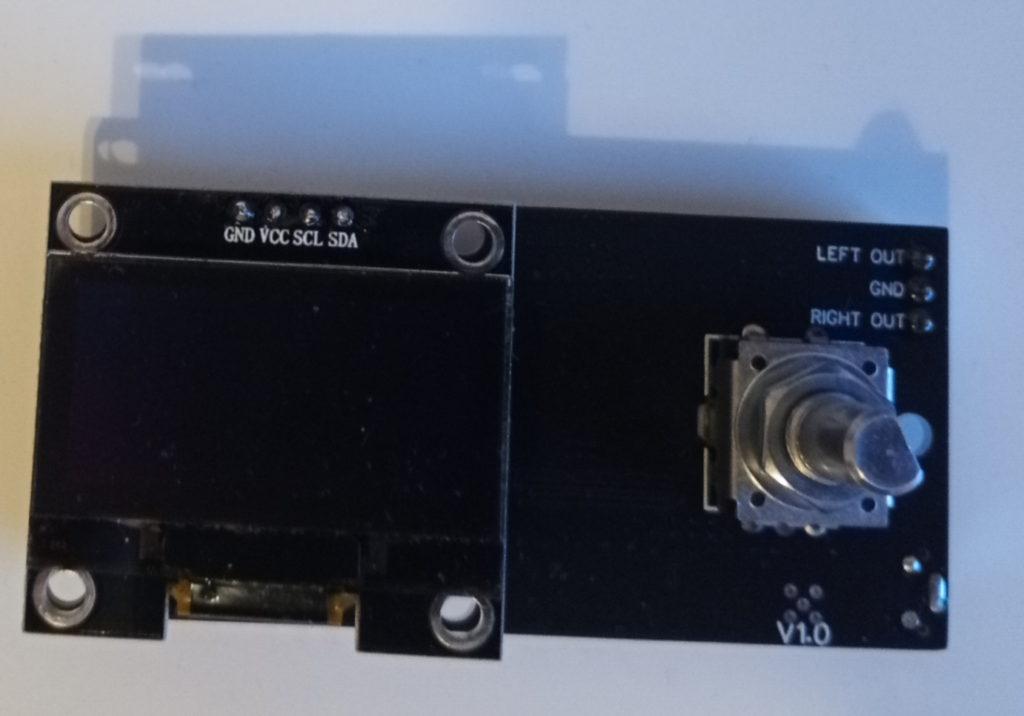
The idea was to build a interface for the universal audio amplifier which can be controlled by an human. For this we need interface components. I really like a rotary encoder with push button and a display for the amplifier information. So lets take a rotary encoder with a push button and a 1.3″ OLED display. The OLED Displays looks later really nice and clean behind a tinted plexiglass. We also need a microcontroller which analyze the rotary encoder data and contains the display graphics. The ESP 32 is a good choice because it is cheap, easy to use, has a lot of storage and a good availability. It has also the option to use it as a bluetooth audio sink or a internetradio. For this functions we need a external I²S audio DAC which put a analog audio signal out. I have made good experience with the PCM510X series from Texas Instruments. It would also be great if we do not need a programmer for the ESP32 and have a communication over USB to control the amplifier over the computer. So we also need a USB to serial converter. A good and cheap choice is the CP2102. It is also on the known ESP 32 node mcu.
Building the PCB:
Lets start to build the PCB. For this i summarized the circuit blocks. We need following blocks:
- rotary encoder with filter
- 1.3″ OLED Display
- ESP32
- Audio DAC
- Power supply
- External connectors for power and logic
- On board programmer
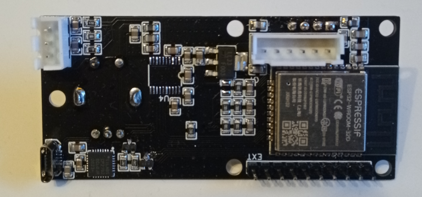
In the circuit these component blocks look like this:
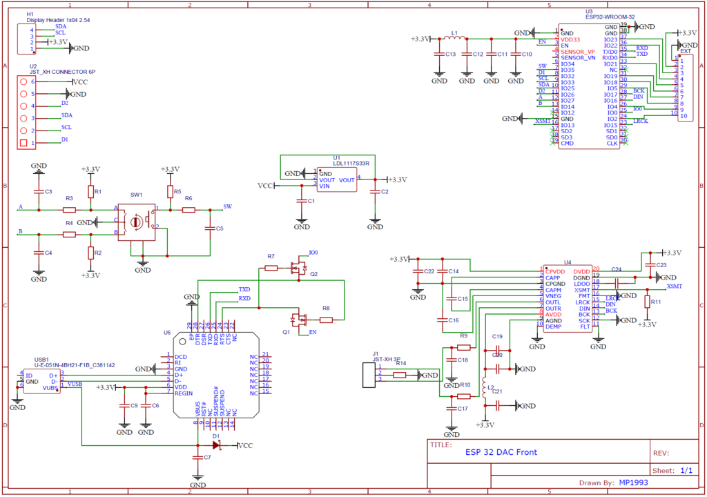
In the top right you can see the ESP32 with some power supply filtering and an external 10 pin header. I route to this header the unused GPIOs. It can be used for a later extension or some customization.
In the bottom right you can see the PCM510X audio DAC. This DAC converts our I²S signals from the ESP32 to an analog audio signal. The analog audio signal from the DAC is routed to a JST XH 3 pin connector.
In the bottom left you can see the CP2102 USB to serial converter. This is detailed described in this post. Over this component we can control the ESP32 from a computer and also program the ESP32.
In the middle left you can see the rotary encoder with some filters. Over this you can control the amplifier.
In the middle middle you can see the voltage regulator. It is an low drop out regulator which has a great power supply rejection ratio. This means, that it reduces the noise from outside over the power supply line.
In the top left you can see the JST XH 6 pin power supply and logic connector to the universal audio amplifier and the connector for the Chinese 1.3″ OLED display board.
The finished PCB:

The PCB is developed to mount it on a 3D printed PCB holder. There are some mounting holes for the display and to mount the PCB to the 3D printed PCB holder. The JST XH 6 connector should be routed to the universal audio amplifier. The 6 pin JST connector contains the power supply and the communication lines to the amplifier. In the top left is a JST XH 3 pin connector which contains the analog audio DAC output signal. At the bottom left is a USB connector for communication and programming over USB.
Writing the Code:
Now its time to write a code for the ESP32. I decide to use the ESP IDF and not arduino, because there are a lot more possibilities in the ESP IDF. The code is still in progress. I will update you soon, if the code is ready.
Other posts about audio: