
A decent lighted cabinet in the hallway of the apartment can look really nice and illuminates indirectly the hallway. In the hallway of my new apartment is a wall mounted cabinet, which suits well for a lighting source under the cabinet. So it would be nice to mount some LEDs under it. The problem is, that there is no power socket for the LEDs. So the LEDs must run from a battery. I did not want to make my own battery in the first step, so i decide to use a USB powerbank for it. The USB voltage is 5V and the LEDs must work with these 5V. I also want, that the LEDs turns on and off automatically if it gets dark. It would also be great if the lightning intensity can be adjusted. I did not found any product which can do all of this, so i decide to make my own LED board with these features and if i can wish me everything, it would also be great if the LEDs can use in every usecase. So i decide to make a LED module which can work without any other board and which can easily linked together .
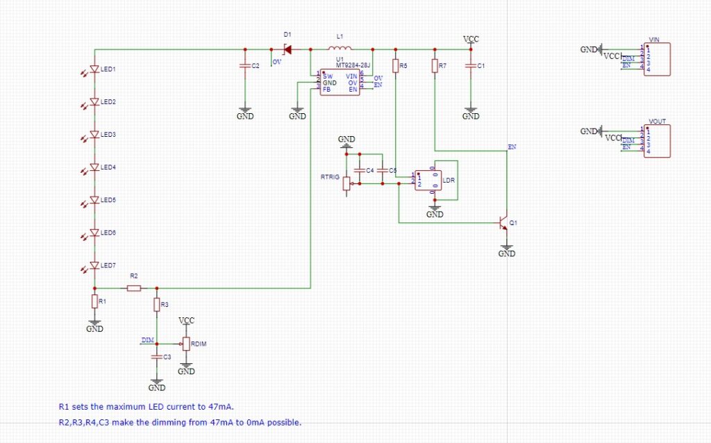
Lets start with the design. I decide to use a Step-Up LED driver which is dimmable and has a enable pin for the automatically turn on feature. The easiest way to get the automatically turn on if it gets dark feature is to use a LDR (light dependent resistor). This resistor changes the value if the light intensity of the surrounding changes. For the light intensity feature of the LEDs was a hint in the datasheet. It can be made over a lowpass and a PWM signal or over a potentiometer. I decide to use a potentiometer to make the module as cheap as possible. After this, i made a circuit diagram of this. You can see it in the following picture.
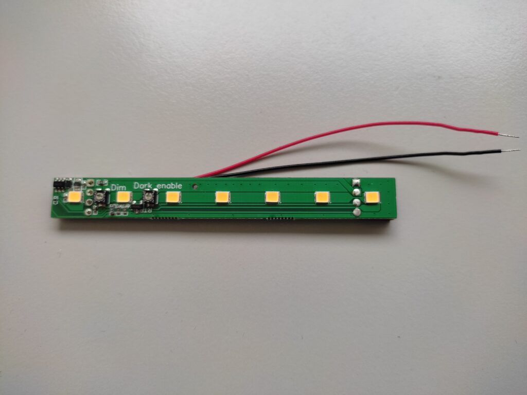
After this i made the layout and order the boards. The boards look like this:
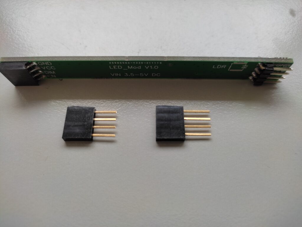
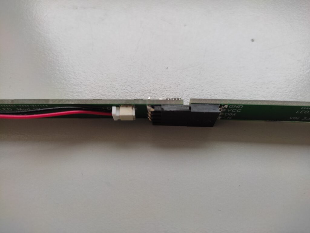
The LED boards can be linked through the 1×04 Header together. I only missed, that one header must be protrude to connect them. So i make a adapter for it. The LDR can be plugged over a JST SH2 connector. This connector is really small and not height. So it fits good under the board. The boards can be mounted with duct tape under the header. Every board has two potentiometer. One for the dark enable feature and one for the light intensity adjustment. So you can decide at which darkness the module should turn on. The Enable and Dim (light intensity) line are shared with all boards, so the light intensity must only be adjusted at one board. I recognize that the dimmable feature can be made a short circuit, if one potentiometer is at VCC and one from an other board is at ground. For the dimmable feature is a change needed, that the current is limited and not so high, if the potentiometer have not the same setting.
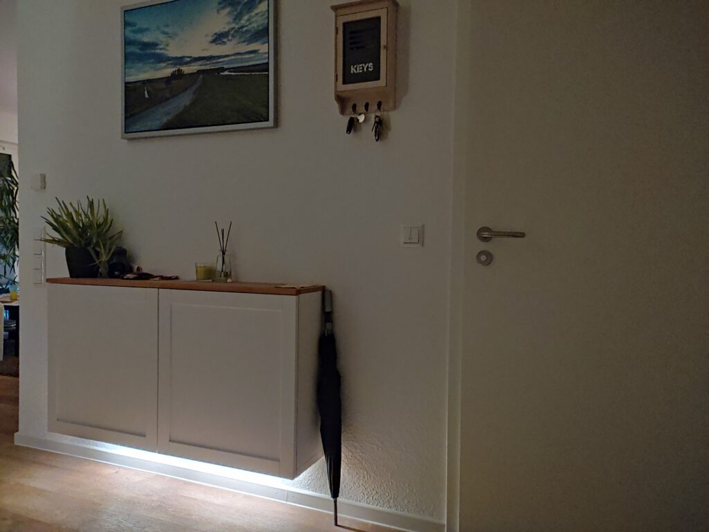
Mounted under the wall mounted cabined and plugged into a USB powerbank looks like this:
Other posts about DIY