Every microcontroller must be programmed. For this you need a programmer. In this Post i show you how the circuit for a ESP 32 programmer should be.
How to program the ESP:
The ESP 32 can be programmed over the UART (RX/TX) interface. To set the ESP 32 in program mode you need to pull the IO0 pin at the start of the ESP 32 low. So just reset the ESP 32 and hold the IO0 pin low. After this the ESP 32 is in program mode and can be programmed over UART.
The circuit:
There are many different circuits for the ESP 32 programmer, but i think this is the most flexible one. It has a CP202 USB to UART Bridge, a switch less circuit which sets the ESP 32 in program mode(R7, R8, Q1, Q2) and the option to power the circuit over USB or an external power supply.
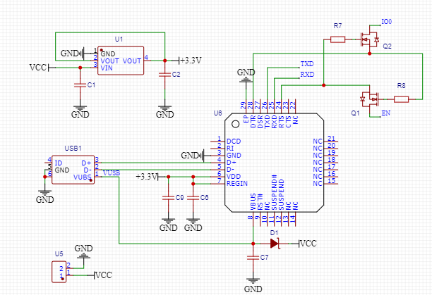
For reliable autoprogramming add a 10k pullup Resistor and a 10uF capacitor to ground at the ESP 32 enable pin. The ESP 32 need a low level at IO0 at reset for starting in programming mode. The Enable and IO0 pin are controlled through the RTS and DTR pins of the CP2102 and the Reset line goes earlier high than the IO0 pin goes low. So you need to hold the reset line a bit longer low. This you can do with the 10uF capacitor at the enable pin. The 10k pullup resistor is for stability in harsh environment.
How to use it:
Connect the TXD, RXD, IO0, EN, +3.3V and ground of the circuit to the ESP 32 you want to flash.
Note: The TXD pin of the programmer should be connected to the RXD pin of the ESP 32 and the RXD pin of the programmer to the TXD pin of the ESP 32. So the RX/TX Pins should be crossed.
Then connect a USB cable to the programmer. Now you can program the ESP 32 via the ESP IDF, Arduino …
Parts:
- C6, C7: 100nF 25V X5R
- C1, C2, C9: 10uF 25V X5R
- R7, R8: 10kΩ
- D1: B5817WS
- Q1, Q2: 2N7002 (Do not use a bipolar junction transistor; the circuit did not work reliable with it)
- U6: CP2102-GMR
- U1: LDL117S33R
- U5: Screw Terminal 2 Pin
- USB1: USB Connector (Input)
Other posts about ESP32