
Content
- ESP 32 WROOM 32D Connection
- ESP 32 WROOM 32D minimal
- Flashing the ESP 32 WROOM 32D
- ESP 32 WROOM 32D Sleep and Wakeup
- Hints
ESP 32 WROOM 32D Connection

ESP 32 WROOM 32D minimal
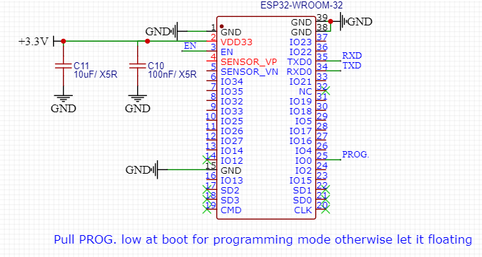
Connect a 3.3V DC power supply.
For programming connect a USB to UART Converter to RX, TX and ground.
For comfortable programming you can also use a USB to UART Converter which has RX, TX, GPIO0 and Enable.
Normally the ESP 32 has an internally pullup at the enable pin. In harsh environment it is possible that the internally pullup is to high. So add a 10k external pullup from enable to +3.3V for a save startup, otherwise the ESP 32 may did not not start reliable. You can measure it. If the ESP 32 won`t start just measure the voltage at the reset pin. If it is not in the area of the Power Supply of the ESP 32 (3.3V) you need an external pullup on the enable pin.
Flashing the ESP 32 WROOM 32D
- Connect the USB to UART Converter to RX, TX and ground. RX and TX should be crossed. This mean RX from the USB to UART Converter should connect to TX from the ESP 32 and TX from the USB to UART Converter should connect to RX from the ESP 32.
- Connect a 3.3V DC power supply to the ESP 32.
- Pull GPIO 0 direct to ground
- Pull reset for a second to ground and let it floating after it.
- Now the ESP 32 is in the programming mode.
Note: There are also programmer who do the job for you automatically.
ESP 32 WROOM 32D Sleep and Wakeup
The ESP 32 has more than one sleep mode, but the most famous one is the deep sleep mode. In the deep sleep mode it consumes only around 10uA. In this mode you can save data in the RTC memory and wake up the ESP 32 over the RTC timer or a RTC GPIO. The ESP 32 has two events to wake up from a RTC GPIO. The first one is the “wake up if any of the selected pins is high” and the second one is the “wake up if all the selected pins are low”. So if the ESP 32 should wakeup from a switch, the switch should be connected to an RTC GPIO and the logic level should be high if the button is pressed because with this configuration you can wakeup from more than one RTC GPIO.
Hints
- Do not connect anything to GPIO 6, 7, 8, 9, 10 and 11. They are connected to the internal flash. The ESP 32 can not communicate with the flash if something is connected.
- GPIO 12 should not pulled high at boot. Otherwise the ESP 32 can not start correctly.
- GPIO 0 should be pulled low for programming. This GPIO is internal pulled high.
- GPIO 1 and 3 are used for programming and debugging.
Other posts about ESP32